

Steel Hall
Will it be possible to fully automate the engineering process of an industrial steel hall and optimize production costs?
« terug naar Integral Analyses Model (IAM)Will it be possible to fully automate the engineering process of an industrial steel hall and optimize production costs?
As part of the SMARTconnection research project, an integral analyses model for an industrial steel hall will be developed. The ultimate goal is to be able to make cost comparisons between variants produced by the parametric model. The development of the model will also help give insight in what is needed to automate the design process of a complete steel structure. Development of the Steel Hall model will be updated on this page-blog.
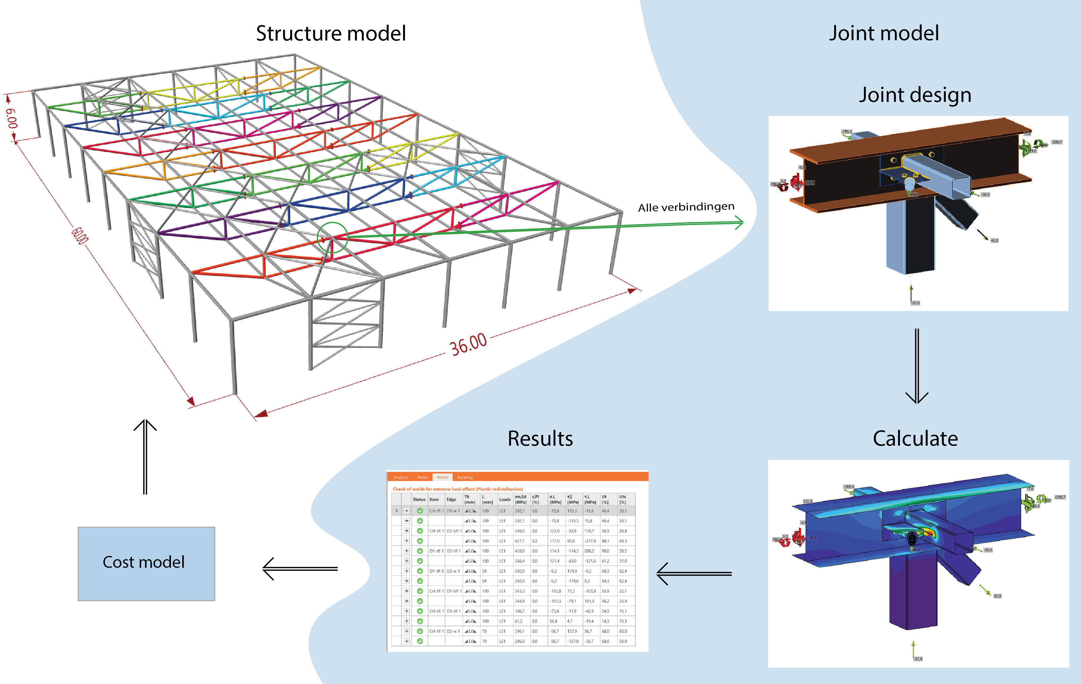
Fig. 1: Iterative integral analyses process
Workflow
To create the model a combination of multiple software packages is needed. The parametric geometry of the structure needs to be created. Afterwards the structure will be analyzed on a global level on strength, stiffness and stability. Joint designs needs to be defined for every joint type occurring in the structure. Finally, both the joint design and the results of the global analysis (N, Vy, Vz, Mt, My, Mz) are needed to analyze the joints. The complete model with all details will be assembled in a BIM-package. From here various amounts (like total weight and total welding volume) can be retrieved. The amounts will be used to define a total price of the steel structure, which is needed to compare different variants from the parametric model.
The following software packages will be used in this model:
Create Geometry: Grasshopper
Analyze Global structure: SCIA or RFEM
Analyze Joints: IDEA Statica Connection
Assemble model in BIM: Tekla Structures
Finding Similar Joints
Various types of joint typologies occur multiple times in the structure. Setting up an automated process all starts with identifying these typologies. These typologies will determine the amount of different joint designs that will occur in the model. All these joint design need to be predefined, because then the automated process knows what to do at each situation.
In the picture below, the joints are identified and given a brand name based on the numbers in hierarchy of the attached beam members. The hierarchy is an integer, where the beam with the lowest number has the highest hierarchy. In this case, the joint typology brand name is defined by ordering the hierarchy numbers of the attached beams chronologically. Therefore, at a joint where beams with a hierarchy of 5, 2, 4 meet, a brand name of "245" is determined.
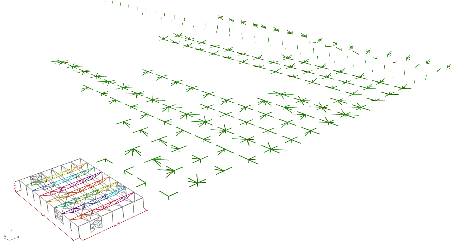
Fig. 2: Joint typologies in project
This method works well enough, but is not completely robust. Especially for the joints that include wind bracing members. In the picture below joints with the same brand name (that are actually different in geometry) are displayed. There are two ways to solve this problem. One is defining a better definition for identifying the joint typologies that will make a distinction between the discussed exceptions. The second solution is defining a joint design template that is parametric enough to cope with wind bracing members coming from different directions.
One of the goals of this research project.is to find a method to easily determine and find the different joint types in a steel structure.
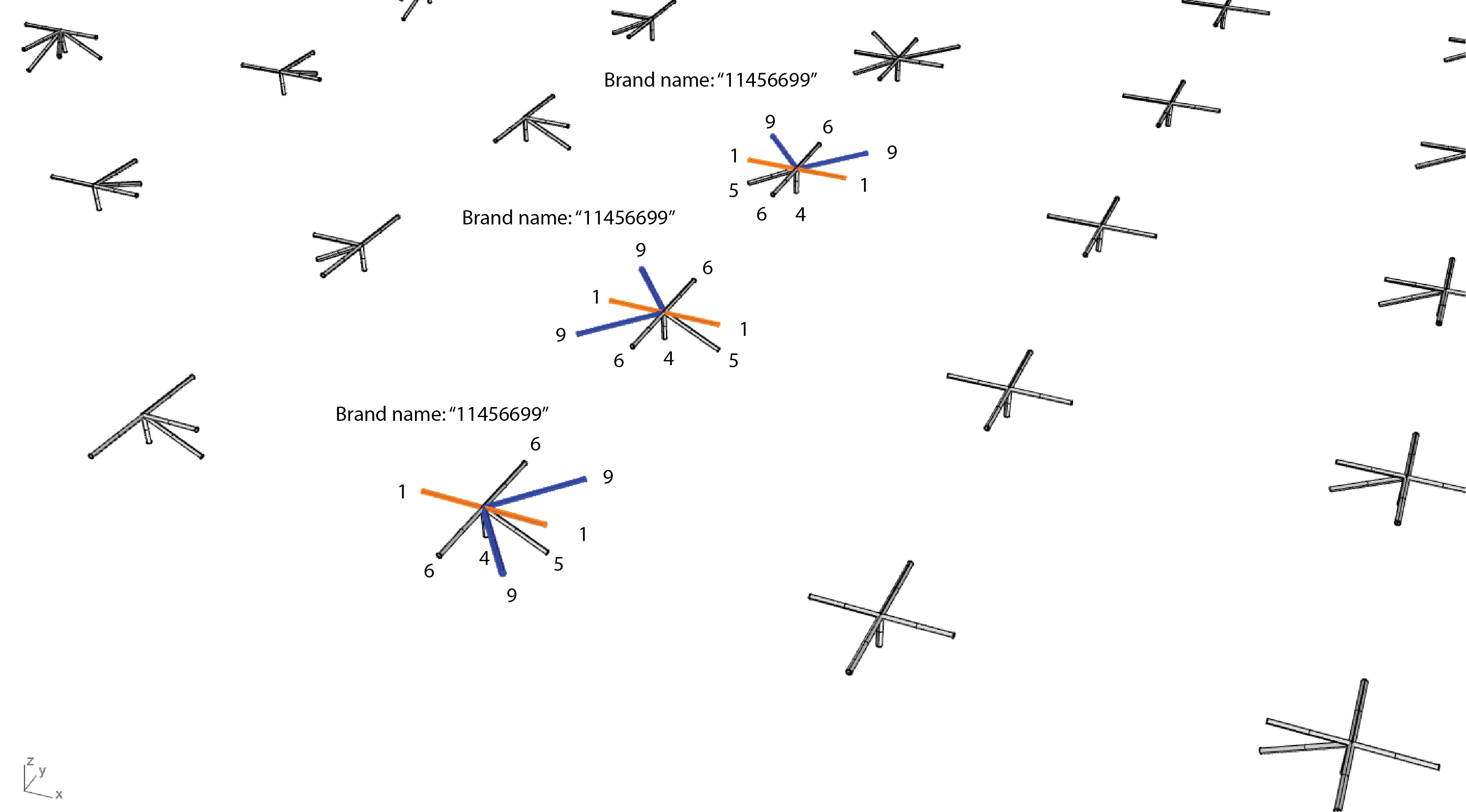
Fig. 3: Defining of Brand names per joint
Predefine joint design templates per joint situation
The picture shows that 17 different joint typologies are found in the structure. For each typology a design will be predetermined and linked. This will create a process where the desired joint design is applied at each joint location.
The joint designs of each typology of the steel hall will later be added to this paragraph.
Finding Governing load combinations
Calculating all the joints of the structure will probably take an excruciating long time. This process can be speed up by finding all load combinations occurring in the project for a particular joint typology and eliminating all non-governing load combinations.
Ideally only the 17 different joint typologies will be calculated with their governing load combinations.
In the pictures below a strategy is shown how to eliminate non-governing load combinations. For readability purposes only N, Vz and Vy are displayed in the example below. All load combination of the joints in the project with the same joint typology are gathered in one table. Afterwards all non-governing combinations will be eliminated. This will be performed by an algorithm that checks if all internal forces of the load case are lower than another load case. If this is true, the load case will be eliminated. For the example shown below, this will cause that only the blue and the green combination in the graph will be used to analyze the joint, speeding up computational time. It should be noted that this example is a simplified version. In reality the different lines will probable be much closer to one another.
To make this strategy work, the found joints of the typology should be exactly equal. Which means, equal geometry (beams, direction) and local coordinate system.
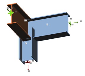
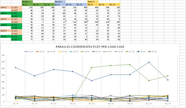
Fig. 4: Finding Governing Load combinations strategy
Cost analyses
Costs will initially be calculated by the total material used, welding volume and the number of unique elements.
File
The Grasshopper file of the Steel Hall can be downloaded at:
https://drive.google.com/drive/folders/1vrWo3RAM8SgA3o7Ef3wh1CLeoN1zuX3W