
Parametric Connections
What are parametric connections and why would you use them? What makes parametric connections, smart connections?
« terug naar SMARTconnectionSteel connections are a direct derivative of the steel structures geometry and cross-sections. Therefore, the changes made to the geometry of the steel structures and its cross-sections has a direct influence on the type of joints that can be designed. When the structure is parametric the connections need to be parametric as well. Due to the connection's dependency on the structure parametric connections can be seen as a 2nd order parametric model.
Rules can be programmed into parametric connections giving them the intelligence to optimize themselves based on the context where they are placed in, those parametric connections can be referred as SMARTconnections. In these smart connections the optimization frame is based on the dimensions of the attached members and the internal forces it must transmit.
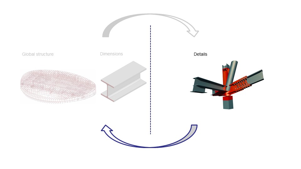
From connection level back to structure level
SMARTconnections give feedback about how the connections fits in the context of the complete structures. It will indicate whether the connection is feasible in this context and if it is, it will show the estimated costs of the connections. This information is useful, since it will give insight into the cost effects of changing the structures geometry or the cross-sections of particular members.
Identifying the joint
As discussed in the page about integral analyses models, similar joint typologies can be identified by using a brand name. When this brand name is known a particular design sequence custom to the joint typology can be made. On this page several examples can be found where a design sequence is applied to a particular joint typology.
This custom design sequence is a programmed script in the form of a grasshopper component. Each of these components has at least two input parameters, the project and the brand name. The project contains all information of the structure, where for example internal forces and beam dimensions can be retrieved from. The referred brand name determines to what joints and what positions this design sequence will be applied.
When the component has defined a solution it will store information of the connection back to the project. This can be the amount of welding volume used in the connection, the weight of extra needed plates. This information can then be translated to costs according to the predefined unit prices for welding, material, bolts etc.
Examples of parametric frame joints
Simple joints
In this component the fin plate connection is optimized. This optimization algorithm is dominantly dependent on two aspects, the acting shear force on the beam and the internal height of the beam. Based on these aspects the algorithm will iterate through various bolt configuration. Starting at 2x M12 it will continue increasing the amount of bolts and increasing the bolt size to M52 until it found a configuration where all criteria are satisfied. Per configuration various checks will be executed. First whether the connection fits within the boundary determined by the beams internal heights, second several structural checks are executed. The results of these checks are displayed in the text message (yellow panel).
In some cases no solution is found. The internal height of the beam is too small to fit a structurally sufficient fin plate connection. When this the case there will be no visualization of the connection.
The source code of this component is open-source available here.
Flexible joints
In this component a flexible joint is created. Based on variable attributes like the presence of stiffeners and the height of a possible haunch, the costs and the calculation connection stiffness in kNm/rad is influenced.
The source code of this component is open-source available here.
Examples of parametric truss joints
Bolted joints
In this component the splice connection is optimized. This optimization algorithm is dominantly dependent on two aspects, the acting axial force in the beam and the internal height and width dimensions of the beam. Similar to the fin plate component, this component will start iterating at 2x M12 and will continue increasing the amount of bolts and increasing the bolt size to M52 until it found a configuration where all criteria are satisfied.
This connection contains three attributes. The thickness of the plates in the splice connection, a reduction factor for the bolts needed to cover prying forces phenomena and the presence of extra stiffeners. All of this attributes influence the generated connection.
The source code of this component is open-source available *here.
*to be updated
Application for parametric truss joints
In the application found below, a typical K-joint of a truss is shown. In a K-joint, steel contractors generally prefer the joint to be a gap joints instead of an overlap joint. Gap joints are easier to built, since the members will be single cut and will therefore be less sensitive for tolerance. In overlap joints, one of the members will be sawn with two cuts, making the joint sensitive for tolerance, since the member needs to be an exact fit.
The application shows how different variables in a parametric connection are of influence in determining whether the joint is a gap joint or an overlap joint.
General information about examples of joints and connections can be found here.