
Integral Analyses Model (IAM)
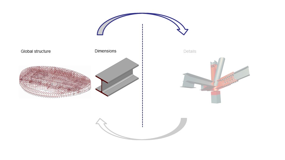
How can global analyses and detail analyses be combined in one parametric model? In this page basic strategies of creating an integral analyses model are discussed.
« terug naar SMARTconnectionAn Integral Analysis Model (IAM), is a model where a structure is analyzed on both structure and detail level. In this page basic strategies needed to develop an IAM are discussed. On the bottom of the page links to IAM examples can be found.
From structure level to connection level
In most cases, steel structures are modeled in finite element method software packages by using 1D elements. In these FEM-models the structure is analyzed on a global level. When all criteria of the structural model are satisfied, information can be extracted to do the detail analysis. This can be a steel connection or a steel joint. In the following paragraph, a strategy will be explained how to extract the information needed for a connection from the FEM-model.
As mentioned before, 1D elements are used when modeling steel structures in FEM software packages. A steel structure will be therefore modeled as wire frame geometry. Within this wire frame, 1D elements are displayed as lines. In which, each line has a starting point and an ending point, see figures below.
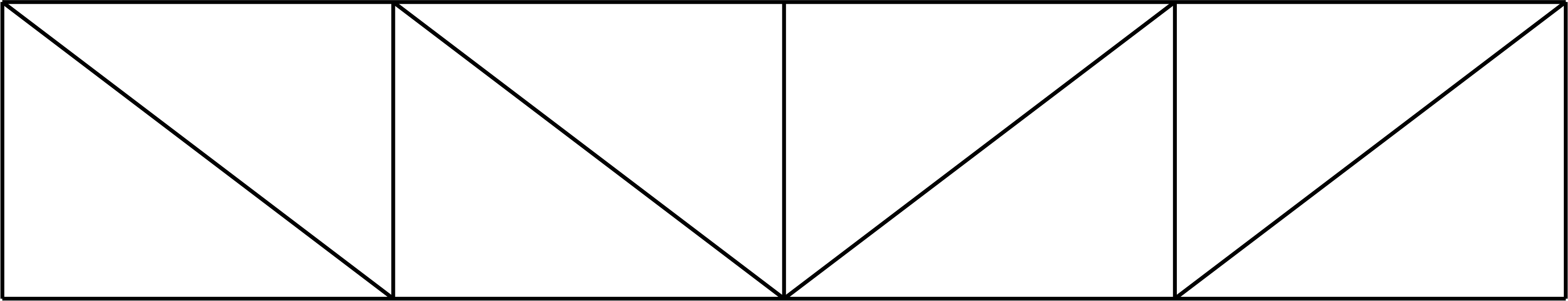
Fig. 1: Lines of wire frame geometry
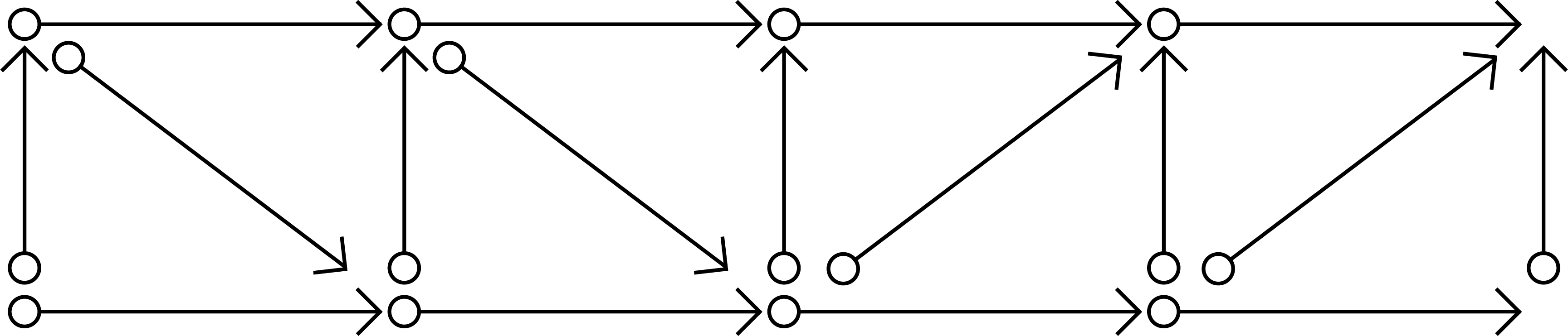
Fig. 2: Start- and endpoints of lines
The information needed to analyze a connection, can be extracted by setting up a rule of logic based on the start and end points of these lines. The lines that occur in the model are stored in a list. To extract the lines from this list that are connected to a desired point, the following rule of logic can be coded:
Rule of logic:
Every line that has a start or end point equal to the desired point is an attached line of the joint.
This rule of logic iterates over the list of lines and will collect attached lines. In the figure below the attached lines of the top left corner are highlighted.
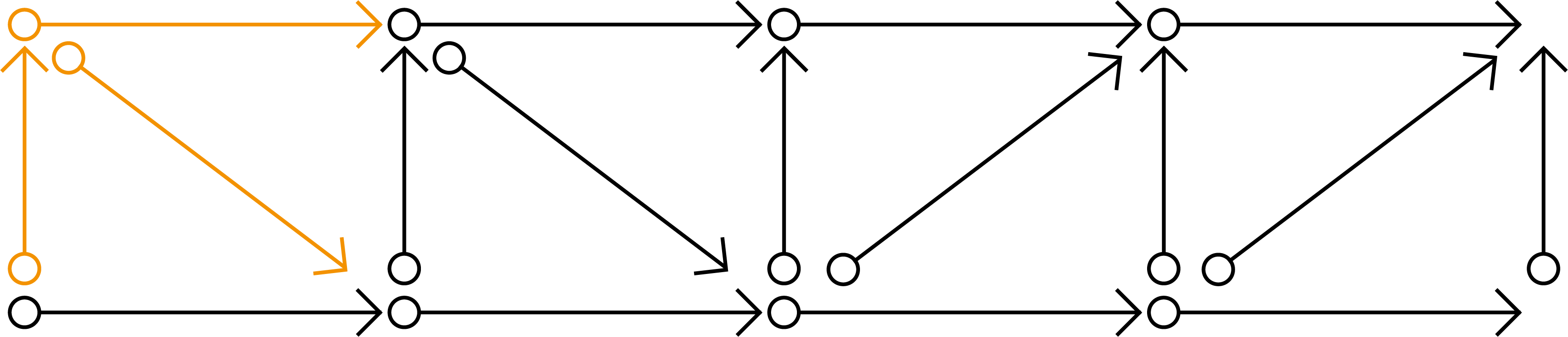
Fig. 3: Selected joint
Information needed for detail analysis:
- Attached geometry (lines)
- Cross-section
- Material (Steelgrade)
- Internal forces per load case (N, Vz, Vy, Mt, My, Mz)
- Hierarchy
Hierarchy of steel structures
Information needed for the detail analysis, which cannot be extracted from the FEM model is the hierarchy of structure. Every steel structures has hierarchy where specific members are continuous and others are ended. The hierarchy determines if a beam in a specific joint is a primary, secondary or tertiary beam and whether a beam is continuous or ended. In the figure below, the joint in the top left corner is displayed. Three beams are attached to this joint, therefore 3! = 3*2*1 = 6 combinations in hierarchy are possible. To make sure a joint is built up as desired, a hierarchy number can be included. The beam with a hierarchy of 1 has the highest hierarchy and will be continuous. The beams with a lower hierarchy (2 and 3) will be cut by beams with a higher hierarchy.
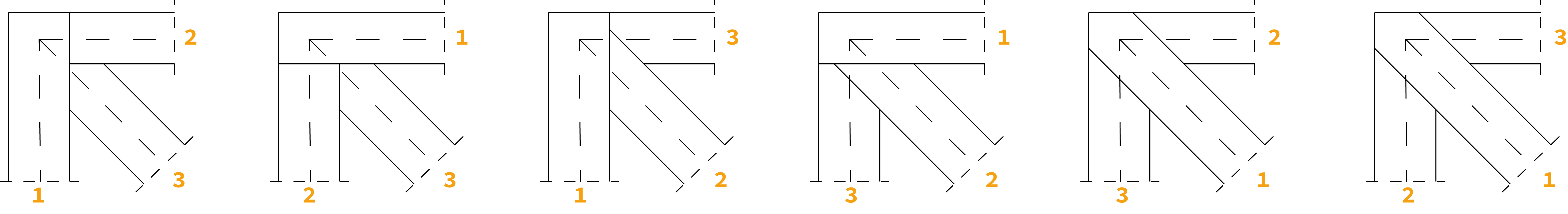
Fig. 4: Possible joint configurations
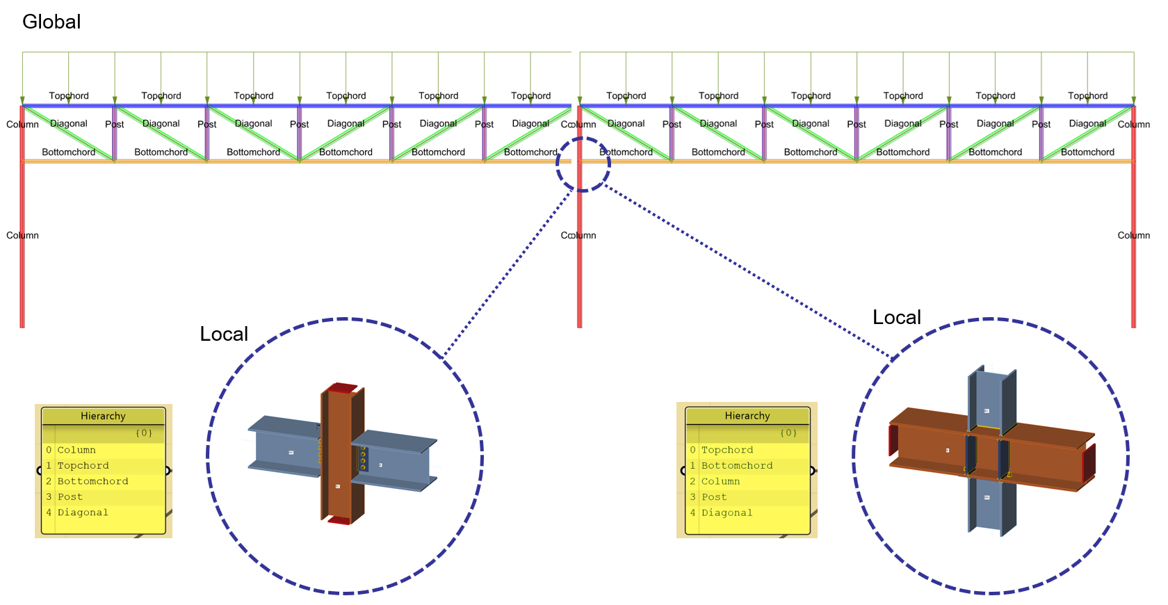
On a structural level, groups of elements can be created. These groups are defined mostly based on their function, the Topchord elements, the Diagonals, etc. The hierarchy of a structure can be assigned to the groups from highest in hierarchy at the top of the list to lowest at the bottom. Using this method, allows the engineer to determine the desired sequence of how beams are connected to one another. The example found in the picture below displays how a different order in hierarchy causes different elements to be continuous.
Identifying similar joint typologies
Defining a hierarchy to your steel structure will give you an additional advantage. Because based on this hierarchy similar joint typologies can be identified.
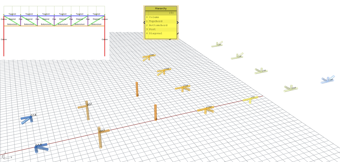
In a joint multiple members are attached and every member is part of a group, where each group has a hierarchy index. When inventorying the hierarchy indexes of all members attached to the joint. These indexes can be put in chronological order, which will provide a serial name (or a brand name) of the joint. Similar joints will have a similar serial/brand name.
For example, the connection in the left corner of the truss in the picture found below consist out of a Topchord-, a Column- and a Diagonal-member. With indexes 1, 0 and 4 respectively. Chronologizing this order gives you the serialname "014". Using this methodology, the right corner will provide you the same serial name. Eventually all joint typologies of a structure can be identified and sorted. The advantage of identifying similar joint typologies, is that these similar joints can be detailed and structurally assessed similarly, this is elaborated further on the page about parametric connections.
It should be noted, that this is just one strategy to identify similar joint typologies. Multiple strategies can be defined, but this strategy is relatively simple and yet quite effective.
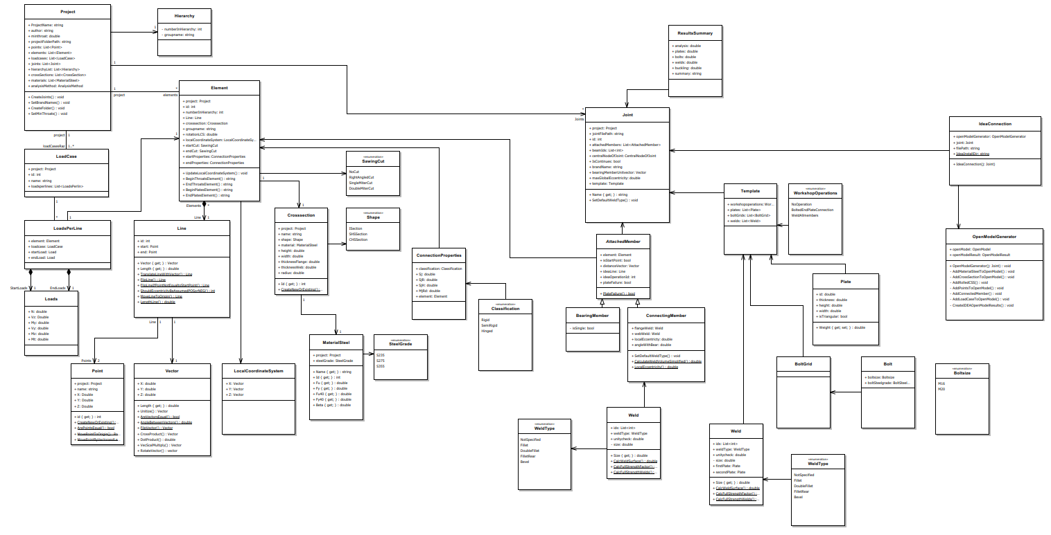
SMARTconnection framework
The key to integrating global and detail analyzes in one system is having a good data structure. This data structure provides the structure to store information in a logical place. During the SMARTconnection research this data structure has continuously been further developed and now forms the backbone of creating an integral anlayses model. A more detailed drawing of the UML diagram displayed in the picture below can be found here.
KarambaIDEA: a product of the SMARTconnection methodology
During the SMARTconnection research, proof of concepts of the methodology have continuously been made. The combination of these proof of concepts caused the creation of a Grasshopper plug-in named KarambaIDEA. In this plug-in steel structures can be optimized based on costs, by combining software for global engineering and detail engineering. In the video found below an informative webinar can be found where functionalities of this plug-in are discussed in combination with live demonstrations.
Examples of IAM's
In the following links, development blogs of various integral analyzes models can be found:
Steel truss with welded connections